By Mike Foley, Founder, Cheap Tubes Inc. & CTI Materials LLC.
Part of the Graphene & CNT Battery Applications hub.
TL;DR
Silicon has roughly ten times the theoretical specific capacity of graphite (4,200 mAh/g vs 372 mAh/g) but expands by approximately 300% during lithiation, pulverizing pure-silicon anodes within a few cycles. Carbon nanotubes and graphene composites address this failure mode through three complementary mechanisms: mechanical strain absorption, electrical conductivity restoration after particle cracking, and SEI stabilization. Production cells with silicon-carbon anodes have shipped since 2024, with target capacity gains of 20–40% at the cell level vs graphite. The polymer binder chemistry (polyimide and polyamide families) is migrating in parallel with the carbon-material selection, and CTI Materials’ Flexiphene patent portfolio (U.S. Patents 10,049,783 and 11,961,630) covers exactly these polymer-nanocarbon composite formulations. This page covers design strategies, material-grade selection, and procurement considerations for silicon-CNT and silicon-graphene anode composites.
The silicon anode capacity vs cycling problem
Lithium intercalation into graphite forms LiC6 — one lithium for every six carbons, a theoretical capacity of 372 mAh/g. Lithium alloying with silicon forms Li15Si4 at room temperature (or Li22Si5 at elevated temperatures) — between 3.75 and 4.4 lithium atoms per silicon, a theoretical capacity of 3,580–4,200 mAh/g depending on alloy phase. At the cell level, replacing graphite with silicon could in principle deliver 20–40% higher energy density at the same cell mass.
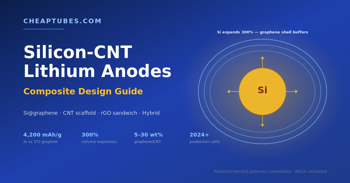
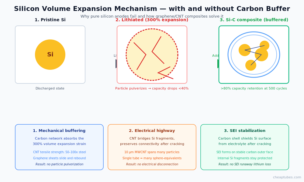
The barrier is mechanical. Silicon expands volumetrically by roughly 300% during full lithiation (and contracts back during delithiation). Pure silicon particles experience this strain at the particle scale on every cycle. The first few cycles crack the particles into smaller fragments; subsequent cycles continue the process; within 50–200 cycles, the silicon has pulverized to the point that electrical contact between fragments — and between the silicon and the current collector — is lost. Capacity drops to a fraction of the initial value.
A second failure mode compounds the first. The newly exposed silicon surfaces formed by each crack consume electrolyte to grow new solid-electrolyte interphase (SEI) layers. SEI growth is irreversible — every new layer permanently removes lithium and electrolyte from the cell’s available pool. After enough cycles, the SEI growth consumes so much lithium that the cell cannot deliver capacity even where particles remain electrically connected.
Together, the volume-expansion problem and the SEI-growth problem make pure silicon anodes commercially impractical. Carbon nanostructures address both.
How CNT and graphene solve the expansion problem
Three mechanisms operate simultaneously when CNT or graphene is incorporated into a silicon anode composite:
1. Mechanical strain absorption. A flexible carbon matrix around silicon particles accommodates the 300% volume change without cracking. Carbon nanotubes have tensile strengths 50–100× that of high-strength steel at one-sixth the density. A web of MWCNT around a silicon particle stretches and rebounds with each lithiation cycle, redistributing the strain across the network rather than concentrating it at the silicon surface. Graphene nanoplatelets and reduced graphene oxide perform a similar function with sheet-like geometry — the silicon expands into the spaces between graphene layers, with the layers sliding past each other to accommodate the change.
2. Electrical conductivity preservation. Even with mechanical buffering, silicon fragments still form during cycling. The decisive question for cycle life is whether the fragments stay electrically connected to the rest of the electrode. Carbon nanotubes act as an electrical highway through the composite — a single 10 µm MWCNT spans dozens of silicon particle diameters and bridges any cracks that develop. Without this electrical network, silicon fragments become electrochemically dead and capacity drops irreversibly.
3. SEI stabilization. A confined silicon particle inside a graphene shell or CNT cage exposes far less surface area to the electrolyte than a free silicon particle. The SEI forms primarily on the carbon outer surface, which is relatively stable once formed. New silicon surface created by internal cracking is shielded from the electrolyte by the carbon shell — preventing the runaway SEI growth that would otherwise consume electrolyte and lithium.
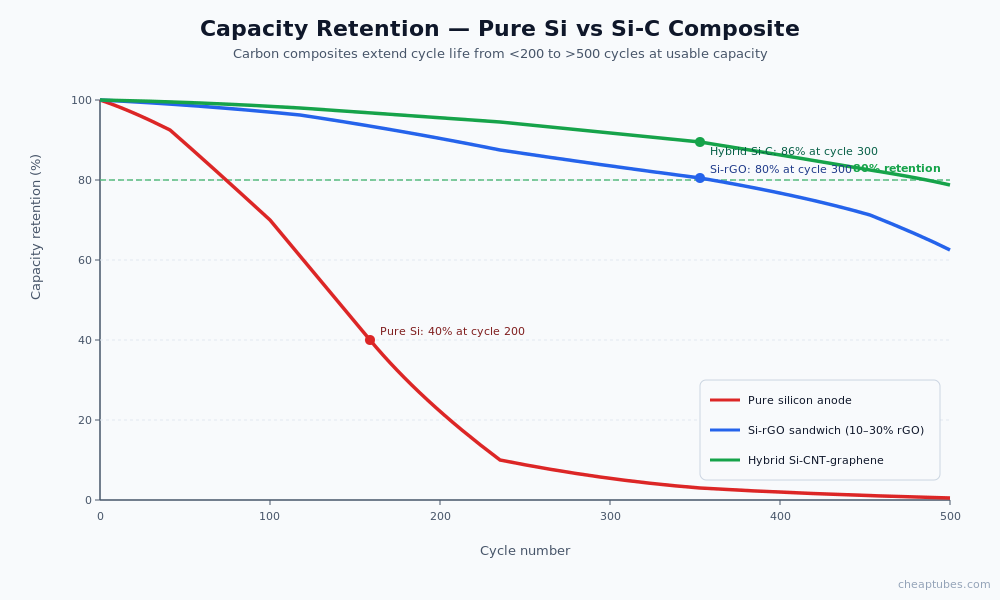
The performance impact is dramatic. Published data on Si-graphene and Si-MWCNT composites shows capacity retention above 80% after 500 cycles at moderate (C/2) rates, compared to <40% retention for unmodified silicon anodes. The best Si-C composite architectures achieve over 1,500 mAh/g at the composite level (still 4× the capacity of graphite) with cycle lives suitable for commercial deployment.
Composite architectures
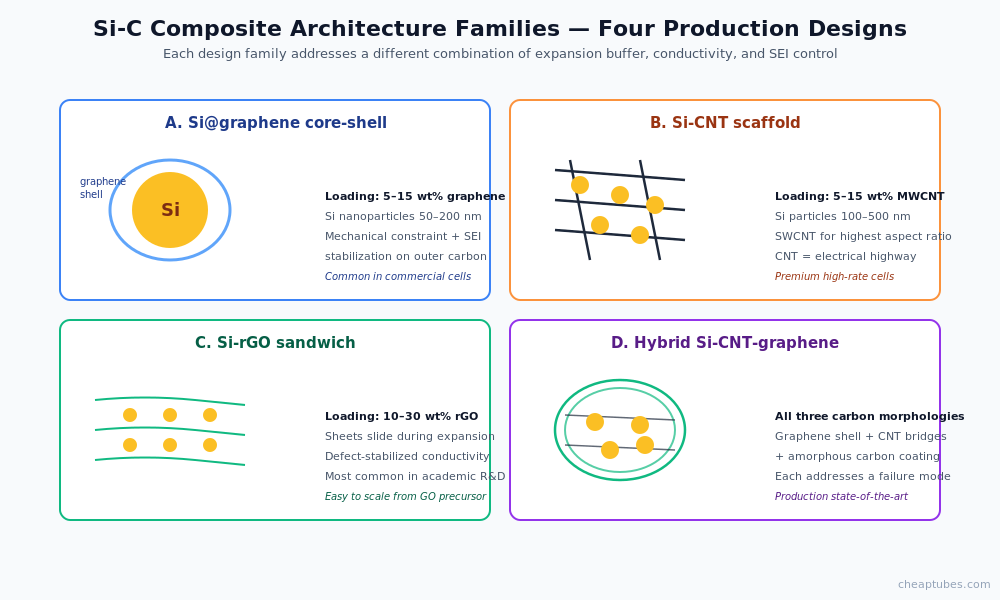
Silicon-carbon anode composites fall into four practical design families:
Si@graphene core-shell. Silicon particles or nanowires encapsulated in a graphene or rGO shell. The shell mechanically constrains expansion and stabilizes the SEI on the carbon outer surface. Commercial implementations typically use 5–15 wt% graphene with silicon nanoparticles in the 50–200 nm range.
Si-CNT yarn or network. Silicon particles dispersed within a CNT scaffold. The CNT network provides both mechanical buffering and the conductive backbone. Optimized formulations use 5–15 wt% MWCNT with silicon particles in the 100–500 nm range. SWCNT is sometimes preferred for the highest conductivity at the lowest mass loading.
Si-rGO sandwich. Silicon particles between sheets of reduced graphene oxide. The rGO sheets slide past each other during expansion, accommodating strain while maintaining a conductive network. Common loadings: 10–30 wt% rGO.
Hybrid Si-CNT-graphene composites. The current state-of-the-art combines all three carbon morphologies — graphene sheets, MWCNT bridges, and amorphous carbon coating — around silicon nanoparticles. Each carbon form addresses a different failure mode. These architectures appear most often in current commercial production cells targeting 20–40% capacity gain over graphite.
The right architecture depends on the silicon morphology (nanoparticle, nanowire, porous), the binder system, and the cell-level targets. Most commercial Si-anode designs use a hybrid approach in production.
Material specifications that matter
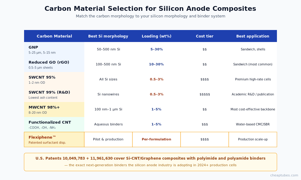
For silicon-anode composite work, the carbon material selection depends on application stage:
Graphene nanoplatelets (GNP). Thickness 5–15 nm, lateral size 5–25 µm. The workhorse for Si-graphene sandwich and shell architectures. Loadings 5–30 wt% of total anode mass. Cheap Tubes’ GNP catalog covers the major lateral size and thickness combinations used in commercial anode work.
Reduced graphene oxide (rGO). Defect-stabilized, conductive, easy to disperse from GO precursor. Lateral size typically 0.5–5 µm. Common loadings 10–30 wt%. Available via the graphene oxide category — most rGO research starts with GO from the same supplier to control the reduction step in-house.
SWCNT 95–99% purity. Best mechanical reinforcement and lowest-mass percolation. Diameters 1–2 nm, lengths 5–30 µm. Loadings as low as 0.5–3 wt% for the conductivity backbone. Premium price but justified in high-spec cells. Available in Cheap Tubes’ SWCNT catalog.
MWCNT 8–20 nm, 98%+ purity. Cost-effective alternative to SWCNT for the conductive backbone. Loadings 1–5 wt%. The 98%+ purity grade is important for anode applications — metal residuals in lower-purity MWCNT can promote unwanted side reactions at the lithium-rich anode interface.
Dispersion strategy. The dispersion problem at the anode interface is acute. Silicon particles, carbon, and binder must form a uniform composite without phase separation. For pilot and production scale, surfactant-stabilized dispersions perform better than dry-mixed formulations — the Flexiphene patented system was originally validated on this class of dispersion and remains the strongest commercial option for surfactant-stabilized silicon-carbon anode formulations.
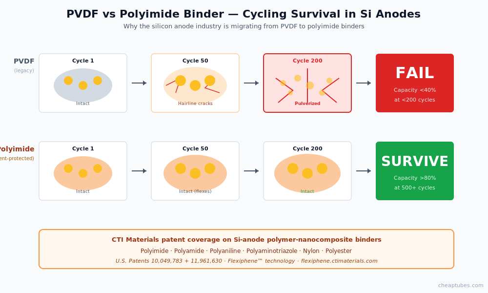
Patent-protected polymer binder coverage for Si-anode composites. The silicon-anode industry is moving from PVDF binders to polyimide and polyamide binder systems that better tolerate silicon volume expansion. Polyimide binders preserve adhesion through repeated 300% volumetric strain cycles where PVDF would crack and delaminate. CTI Materials holds patent coverage (U.S. Patents 10,049,783 and 11,961,630) on CNT + graphene/GO/GNP composites with polyimide, polyamide, polyaniline, polyaminotriazole, nylon, and polyester matrices — covering the exact next-generation binder chemistries the silicon anode industry is adopting. For Si-anode R&D and pilot teams qualifying these binder systems, the Flexiphene patented dispersion technology provides validated performance data and freedom-to-operate on the composite chemistry.
The 2024 Tark & Lee work (Korea Electrotechnology Research Institute) demonstrates the importance of this combined approach — dispersant-free N-doped SWCNT + graphene encapsulation of silicon, achieving accelerated Li-ion transport and improved cycle stability. The dispersion engineering and polymer-binder selection are inseparable from the carbon-material specification when scaling Si-C anodes to production.
Cheaptubes products for silicon-anode applications
- Graphene Nanoplatelets — multiple lateral sizes and thicknesses suitable for Si-graphene shells and sandwich structures
- Graphene Oxide / Reduced Graphene Oxide — for rGO-based sandwich architectures
- Single-Walled Carbon Nanotubes — 95% to 99.9% purity grades for premium and R&D anode work
- Multi-Walled Carbon Nanotubes — 98%+ purity for cost-effective conductive backbone
- Functionalized CNT — -COOH, -OH, -NH2 functional groups for water-based binder compatibility
- Flexiphene surfactant-stabilized dispersions — for scale-up of silicon-carbon anode slurry where dispersion uniformity drives yield. NASA-validated, free sample request available.
For custom silicon-carbon formulations or tonnage supply, contact Cheap Tubes Inc. directly.
Authoritative external references
- Chou, S.-L. et al. — first Si/graphene composite anode demonstrating 1168 mAh/g stable over 30 cycles, foundational paper (2010) (Electrochem. Commun.)
- Ng, S.H. et al. — Si nanoparticles–graphene paper composite achieving >2200 mAh/g over 50 cycles (2010) (Chem. Commun.)
- Magasinski, A. et al. — silicon-graphene composite anodes (2010) (Nature Materials)
- Chan, C. K. et al. — silicon nanowire anodes (2008) (Nature Nanotechnology)
- Wu, H. et al. — stable silicon-graphene hybrid anodes (2013) (Nature Communications)
- Tark, H.J. & Lee, D.G. — dispersant-free colloidal engineering of Si-nanocarbon hybrid anode using N-doped SWCNT + graphene encapsulation, accelerated Li-ion transport (2024) (Advanced Functional Materials)
- Recent comprehensive review — CNT and graphene for relieving volume expansion in Si-based composite anodes (2024) (Carbon, 218, 118726)
- Tailoring rGO sheet size for Si@rGO composite anodes (2024) (ACS Appl. Mater. Interfaces)
- DOE Vehicle Technologies — Si anode roadmap (Annual Merit Reviews)
(External links reflect representative peer-reviewed literature; no endorsement implied.)
Frequently asked questions
Why does silicon need carbon at all — why not pure Si nanoparticles?
Pure silicon nanoparticles cycle better than micron-scale silicon (because smaller particles tolerate strain), but they still suffer from SEI runaway growth and electrical disconnection after enough cycles. The carbon network is what extends cycle life from a few dozen cycles to several hundred and ultimately several thousand cycles needed for commercial cells.
What silicon loading is typical in commercial Si-C anodes?
Most commercial Si-C anode chemistries use 5–20 wt% silicon in a graphite-dominant matrix. Some next-gen designs push to 30–40% silicon. Pure silicon anodes (>80% Si) remain primarily R&D.
Is SWCNT necessary or is MWCNT sufficient?
For most commercial Si-C anode formulations MWCNT (98%+, 8–20 nm) delivers excellent performance at significantly lower cost. SWCNT is favored in premium cells, fast-charge applications, and academic R&D where the highest conductivity and best mechanical reinforcement at lowest mass justify the premium price.
What’s the difference between GO, rGO, and graphene in Si anodes?
Graphene (GNP, mechanically exfoliated, CVD) has the highest electrical conductivity but is hardest to disperse. Graphene oxide (GO) has oxygen functional groups that improve dispersion in polar solvents but reduce conductivity — useful as a precursor. Reduced graphene oxide (rGO) restores most of the conductivity while keeping useful surface defects that anchor silicon particles. Most Si-anode work uses rGO as the practical compromise; pure CVD graphene is reserved for fundamental studies.
How does the carbon affect first-cycle coulombic efficiency?
First-cycle coulombic efficiency (CE1) is critical for Si-anode cells because every percentage point of irreversible capacity loss in the anode requires extra cathode material to compensate. Pristine silicon CE1 is typically 60–80%. Si-C composites with well-engineered SEI stabilization achieve 85–92% CE1 — close to but still below graphite’s 92–95%. Composite design and pre-lithiation strategies (chemical or electrochemical) are active development areas for closing this gap.
Continue reading
- Hub: Graphene & CNT Battery Applications
- Previous spoke: CNT Cathode Conductive Additive
- Next spoke: Graphene & MXene Supercapacitor Electrodes
- Buying guides: SWCNT, MWCNT, Graphene Nanoplatelets
About the author
Mike Foley is the founder of Cheap Tubes Inc. and CTI Materials LLC. He holds 2 granted U.S. patents (10,049,783 and 11,961,630) in carbon nanomaterial applications, with additional patents in prosecution. His patented materials were selected by NASA for the Enceladus mission as a dual-capacitance layer in ion-selective electrodes. Mike has supplied carbon nanomaterials to battery R&D and production for 21 years.
Application Spotlight: PPBT/SWCNT Stress-Relieving Coating Delivers 1,894 mAh/g on Silicon Microparticle Anodes — Gueon, Ren, Sun et al. (Reichmanis group, Lehigh + Brookhaven + Stony Brook). 1894 mAh/g reversible capacity at 300 cycles (2 A/g), 0.027%/cycle decay, 85% ICE, 3.3x improvement over pristine Si MP, 45% less tensile-stress variation than SWCNT-only coatings. ACS Applied Energy Materials 7(17), 7220-7231 (2024).