By Mike Foley, Founder, Cheap Tubes Inc. & CTI Materials LLC.
Part of the Graphene & CNT Battery Applications hub.
TL;DR
Multi-walled carbon nanotubes (MWCNT) have become the preferred conductive additive in lithium iron phosphate (LFP) and nickel-manganese-cobalt (NMC) cathodes for lithium-ion cells. At 0.3–1.5 wt% loading they deliver the same percolation network that 2–5 wt% carbon black provides — freeing up to 4 percentage points of mass for active material and raising cell-level energy density by 1–4%. The right grade is typically MWCNT 8–20 nm outer diameter, 95–98% purity, dispersed via surfactant or high-shear pre-mixing into NMP or aqueous binder systems. This page covers the mechanism, the LFP/NMC/LCO selection differences, and the specifications that determine performance and reproducibility.
The problem with carbon black
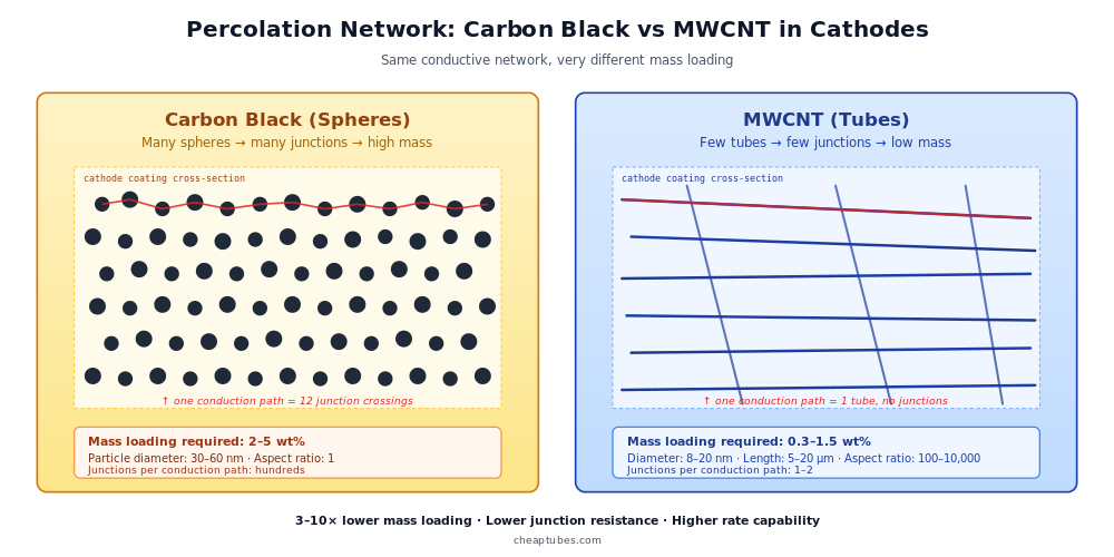
For three decades, the standard conductive additive in lithium-ion cathodes has been carbon black — typically Super P, Ketjen Black, or similar acetylene-black variants. Carbon black is cheap, well-characterized, and easy to disperse. Its limitation is geometry: carbon black particles are spheres of 30–60 nm diameter that conduct only between adjacent particles. Building a continuous electrical network through a thick cathode coating requires a percolating chain of touching spheres — which in turn requires a high mass loading, typically 2–5 wt% of the cathode formulation.
That 2–5 wt% comes out of the active-material budget. Every percentage point allocated to carbon black is a percentage point not contributing to capacity. In a thick LFP cathode targeting 200 mAh/g of active-material capacity, displacing 4 wt% carbon black with 1 wt% conductive additive reclaims 3 wt% of mass for additional active material — directly raising cell-level energy density.
The second problem with carbon black is its rate-capability ceiling. Spherical particle networks have many junction points, each a contact-resistance bottleneck. At high charge or discharge rates, the voltage drop across these junctions limits how fast the cell can deliver power. Cells targeting fast-charging consumer applications, electric-vehicle high-power discharge, or grid frequency response benefit from a conductive additive that minimizes the number of junctions in the current path.
These two limitations — mass burden and junction resistance — are exactly the problems carbon nanotubes solve.
Why MWCNT works as a cathode conductive additive
A multi-walled carbon nanotube has an aspect ratio (length / diameter) typically between 100 and 10,000. A single 10 µm MWCNT 15 nm in diameter spans an entire cathode coating in one continuous conducting path. Where carbon black requires hundreds of touching spheres to bridge a cathode, a single CNT bridges it directly with zero internal junctions.
Percolation threshold. Classical percolation theory predicts that anisotropic conductive fillers — long thin objects like nanotubes or fibers — reach a connected network at a critical volume fraction inversely proportional to their aspect ratio. For spherical particles, percolation requires roughly 16 vol%. For nanotubes with aspect ratio 1,000, percolation can be achieved at 0.05 vol% or lower. Translated into mass: where carbon black needs 2–5 wt% to percolate, MWCNT needs 0.3–1.5 wt%. This 3–10× reduction in conductive-additive mass is the fundamental commercial driver.
Junction reduction. Beyond mass savings, the long-tube geometry eliminates the multi-junction resistance ladder of a sphere network. Most current paths through a cathode loaded with MWCNT cross only one or two tubes, vs hundreds of carbon-black-particle contacts. The result is lower internal resistance, higher rate capability, and reduced heating during fast charging.
Mechanical reinforcement. Carbon nanotubes also provide mechanical reinforcement to the cathode coating during cycling. Cathode active materials such as NMC undergo small but cumulative volume changes during lithiation and delithiation. The CNT network reduces the cracking and electrical disconnection that otherwise progressively degrade cycle life — a secondary but measurable benefit, especially in high-nickel NMC formulations.
The combination of lower mass loading, lower junction resistance, and mechanical reinforcement is why production cell manufacturers have either adopted MWCNT or actively qualified it across all major cathode chemistries.
LFP vs NMC vs LCO — application-specific considerations
The right MWCNT grade and loading vary by cathode chemistry.
Lithium iron phosphate (LFP). LFP has intrinsically low electronic conductivity (~10-9 S/cm), making it the chemistry that benefits most from a high-conductivity additive. MWCNT loadings of 0.5–1.5 wt% are typical in commercial LFP formulations. LFP-cell makers — particularly those targeting energy-storage-system (ESS) and entry-tier electric vehicle applications — have led the industrial adoption of CNT in cathodes. Combination strategies (low CNT + reduced carbon-black fraction) are also common in cost-sensitive LFP cells.
Nickel-manganese-cobalt (NMC) and high-nickel variants. NMC has higher intrinsic conductivity than LFP, so the conductivity benefit of CNT is smaller — but the mechanical reinforcement benefit is larger because NMC undergoes more volume change per cycle. Typical loadings are 0.3–1.0 wt% MWCNT. High-nickel NMC (NMC811, NMC9-series) particularly benefits from CNT because the mechanical-reinforcement effect mitigates the rapid cycle-life decay of high-nickel chemistries.
Lithium cobalt oxide (LCO). LCO retains a niche in consumer electronics requiring high volumetric energy density. CNT is used in some premium LCO cells primarily for the mass-saving benefit; loadings of 0.3–0.8 wt% are typical.
For all three chemistries, the CNT specification range converges: 8–20 nm outer diameter, 5–20 µm length, 95–98% purity. The differences are loading and the relative emphasis on conductivity vs mechanical benefits.

Material specifications that matter
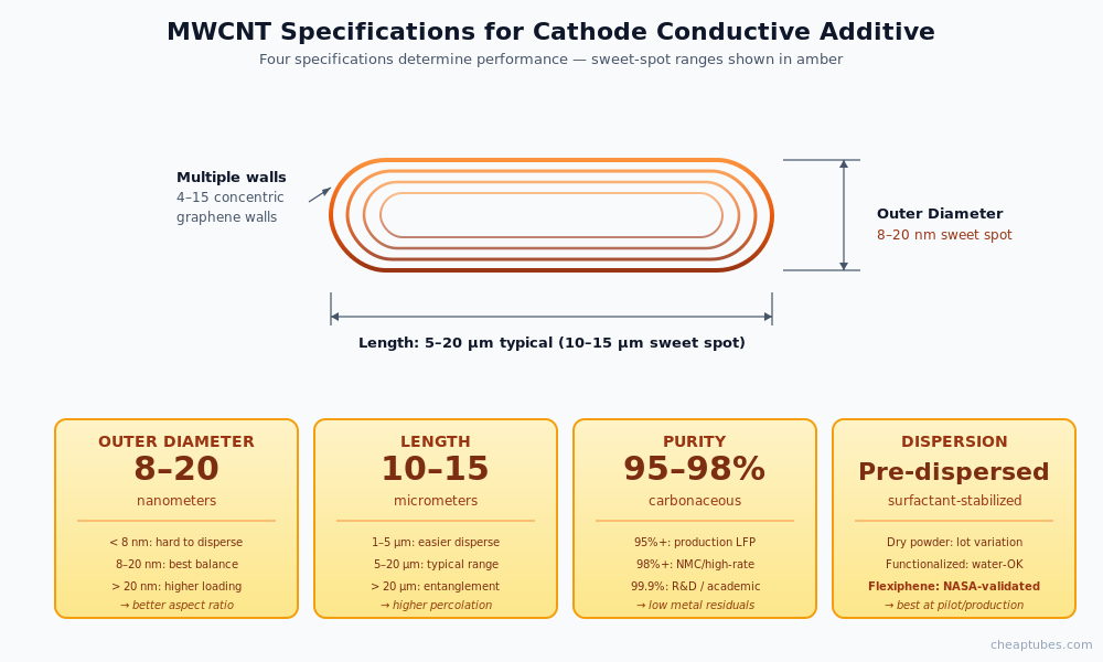
For a cathode conductive additive, four MWCNT specifications determine the working performance:
Outer diameter (8–20 nm). Smaller-diameter MWCNT has higher aspect ratio and percolates at lower loading, but is harder to disperse and more expensive to produce. Larger-diameter MWCNT (20–50 nm) is easier to handle but loses some of the percolation benefit. The 8–20 nm range is the practical sweet spot for cost-performance balance in production cells.
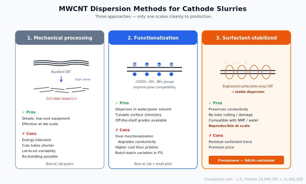
Length (5–20 µm). Longer tubes improve percolation efficiency but are more prone to entanglement and bundling. Shorter tubes (1–5 µm) disperse more easily but require slightly higher loading. Most commercial cathode formulations target 10–15 µm average length. Note that aggressive sonication or ball milling during dispersion can cut tubes shorter — this is a meaningful effect in pilot scale-up.
Purity (95–98%). Carbonaceous purity above 95% is essential — non-carbon impurities (catalyst metal residues, amorphous carbon) can create local hot spots, increase internal cell impedance, or contribute to side reactions at the cathode interface. For most production LFP and NMC, 95–98% MWCNT is sufficient. Premium and high-rate cells use 99%+. R&D and academic studies often specify 99.9% to eliminate metal-residue interference with measurement.
Dispersion behavior. This is the most under-appreciated specification. Two MWCNT lots with identical nominal specs (same diameter, length, and purity) can disperse very differently into the same NMP or water-based binder system. Dispersion behavior depends on the manufacturing CVD conditions, the post-processing (acid treatment, annealing, surface treatment), and the bundling state of the as-produced material. The most reliable strategy is to pre-disperse MWCNT in a surfactant-stabilized formulation rather than disperse from dry powder — this is exactly the gap that the Flexiphene patented surfactant technology addresses for production-scale dispersion.
A useful rule: if your dispersion takes more than 30 minutes of high-shear processing per batch to look uniform, the dispersion failure mode will dominate your batch-to-batch variability long before the MWCNT specification does.
Patent-protected polymer binders. A growing share of production cathode formulations is migrating from PVDF/NMP binder systems to water-based polyamide or polyamide-blended binders, and to polyimide binders for high-temperature applications. CTI Materials holds patent coverage (U.S. Patents 10,049,783 and 11,961,630) on CNT + graphene/GO/GNP composites with polyamide, polyimide, polyaniline, polyaminotriazole, nylon, and polyester polymer matrices — the exact binder chemistries the cathode industry is adopting. For production buyers transitioning to these next-generation binders, the Flexiphene patented system provides both the dispersion technology and freedom-to-operate on the polymer-composite chemistry.
Practical formulation guidance
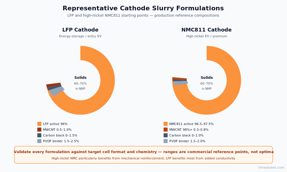
A representative starting formulation for an LFP cathode:
| Component | Loading (wt%) | Notes |
|---|---|---|
| LFP active material | 95.5–96.5 | Carbon-coated LFP particles, 0.5–2 µm |
| MWCNT (8–15 nm, 95%) | 0.5–1.0 | Pre-dispersed in NMP or surfactant-stabilized aqueous |
| Carbon black (Super P or equivalent) | 0–1.5 | Optional; 0.5 wt% common in cost-tuned formulations |
| PVDF binder | 1.5–2.5 | NMP solvent system |
| Solvent (NMP) | to slurry viscosity | Typically 60–70% solids in slurry |
For a high-nickel NMC811 cathode the loading shifts:
| Component | Loading (wt%) |
|---|---|
| NMC811 active material | 96.5–97.5 |
| MWCNT (8–15 nm, 98%) | 0.3–0.8 |
| Carbon black | 0–1.0 |
| PVDF binder | 1.5–2.0 |
The exact loading depends on coating thickness, current density target, and binder system. The ranges above are commercial-reference points, not absolute optima — every formulation requires validation on the target cell format and chemistry.
Cheaptubes products for cathode conductive additive applications
- Industrial-Grade MWCNT — production-scale MWCNT in 8–20 nm OD, 95–98% purity. Available by the kilogram and tonnage. Ships in customer-spec packaging (drums, super-sacks).
- CNT Composite Additive — dedicated SKU optimized for conductive-additive applications, with characterization data tuned for percolation performance.
- CNT Masterbatches — pre-dispersed concentrates in PA6, PC, ABS, PP, and other engineering polymers for direct loading into cathode binder systems.
- Multi-Walled Carbon Nanotubes (full catalog) — for R&D and pilot work requiring specific OD, length, or purity grades not available in the industrial line.
- Flexiphene surfactant-stabilized dispersions — for dispersion-limited production scale-up. NASA-validated, U.S. patented, free sample request available for qualifying applications.
For custom MWCNT specifications (specific OD distribution, length cuts, surface treatment), or for tonnage supply contracts, contact Cheap Tubes Inc. directly — the standard catalog covers ~85 SKUs but custom production runs are available for production buyers.
Authoritative external references
- Tang, J., Pang, J. & Wang, J. — covalent 3D CNT@rGO nano-hybrid for high-efficiency LiFePO4 cathode conductivity, current commercial-relevance state-of-the-art (2025) (Advanced Science)
- Tong, X. et al. — comprehensive review of CNT applications in lithium-ion batteries including freestanding anodes, conductive additives, and current collectors (2025) (Carbon Energy)
- Hassoun, J. et al. — full LIB cell with graphene anode + LiFePO4 cathode achieving 190 Wh/kg energy density (2014) (Nano Letters)
- Su, F.-Y. et al. — single-walled CNT as a conducting additive for LFP cathodes (2011) (Carbon)
- Sehrawat, P. et al. — review of CNT-based composite cathode materials for lithium-ion batteries (2022) (Energy Reports)
- DOE Office of Vehicle Technologies — battery cell engineering Annual Merit Review presentations
(External links reflect representative peer-reviewed literature; no endorsement implied.)
Frequently asked questions
What’s the typical MWCNT loading in a commercial LFP cathode?
0.5–1.0 wt% as the sole conductive additive, or 0.2–0.5 wt% MWCNT combined with 0.5–1.5 wt% carbon black. The exact loading depends on coating thickness, target rate capability, and the LFP particle morphology. Cost-optimized formulations often use the combined approach because residual carbon black is cheaper than equivalent CNT mass.
Can SWCNT replace MWCNT in cathodes?
Technically yes — SWCNT achieves percolation at 0.05–0.2 wt%, even lower than MWCNT — but the per-gram cost of SWCNT is 5–20× higher. SWCNT in cathodes appears in premium niche cells (e.g., high-rate consumer or aerospace applications) where the conductivity-per-gram advantage justifies the cost premium. For mainstream LFP and NMC production, MWCNT remains the better cost-performance choice.
What MWCNT diameter is best for LFP cathodes?
8–15 nm outer diameter is the typical commercial sweet spot. Smaller diameters (5–8 nm) reach percolation at lower loading but are harder to disperse and more expensive. Larger diameters (20–50 nm) are easier to handle but require slightly higher loading.
Is MWCNT compatible with both NMP and aqueous (water-based) binder systems?
Yes, with caveats. NMP-based PVDF binder systems are the legacy standard and disperse pristine MWCNT readily with high-shear mixing. Water-based binder systems (CMC/SBR) are increasingly popular for cost and environmental reasons but require either a surfactant-stabilized MWCNT dispersion or functionalized MWCNT to disperse uniformly. Surfactant-stabilized formulations like Flexiphene are particularly well-suited to aqueous cathode systems.
Does MWCNT replace carbon black entirely or only partially?
Both approaches are used in production. Full replacement (MWCNT only, 0.5–1.5 wt%) maximizes the energy-density gain but requires the most careful dispersion control. Partial replacement (MWCNT 0.2–0.5 wt% + carbon black 0.5–1.5 wt%) is more forgiving in production and achieves most of the energy-density benefit. Cost-tuned formulations often favor partial replacement; energy-density-tuned formulations favor full replacement.
Continue reading
- Hub: Graphene & CNT Battery Applications — overview and material selection across all four battery application categories
- Spoke 2: Silicon-CNT and Graphene Lithium-Ion Anodes
- Spoke 3: Graphene & MXene Supercapacitor Electrodes
- Spoke 4: CNT & Graphene in Li-S, Li-air, and Solid-State Batteries
- Buying guide: Multi-Walled Carbon Nanotubes Buying Guide
About the author
Mike Foley is the founder of Cheap Tubes Inc. and CTI Materials LLC. He holds 2 granted U.S. patents (10,049,783 and 11,961,630) in carbon nanomaterial applications, with additional patents in prosecution. His patented materials were selected by NASA for the Enceladus mission as a dual-capacitance layer in ion-selective electrodes. Mike has supplied carbon nanomaterials to battery R&D and production for 21 years.